


DSO 1122S
820,00 €
Hantek DSO 1122S (120 MHz) is a digital oscilloscope suitable for use in harsh industrial environments, but also for work in the field.
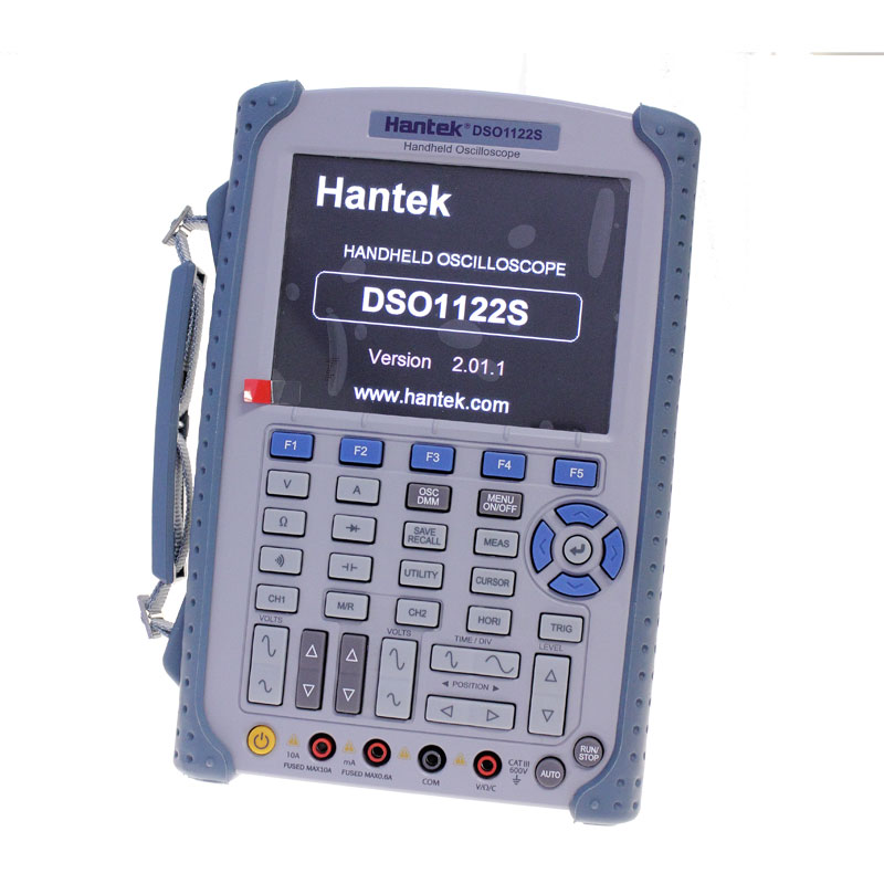
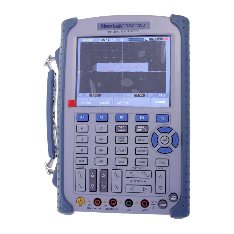
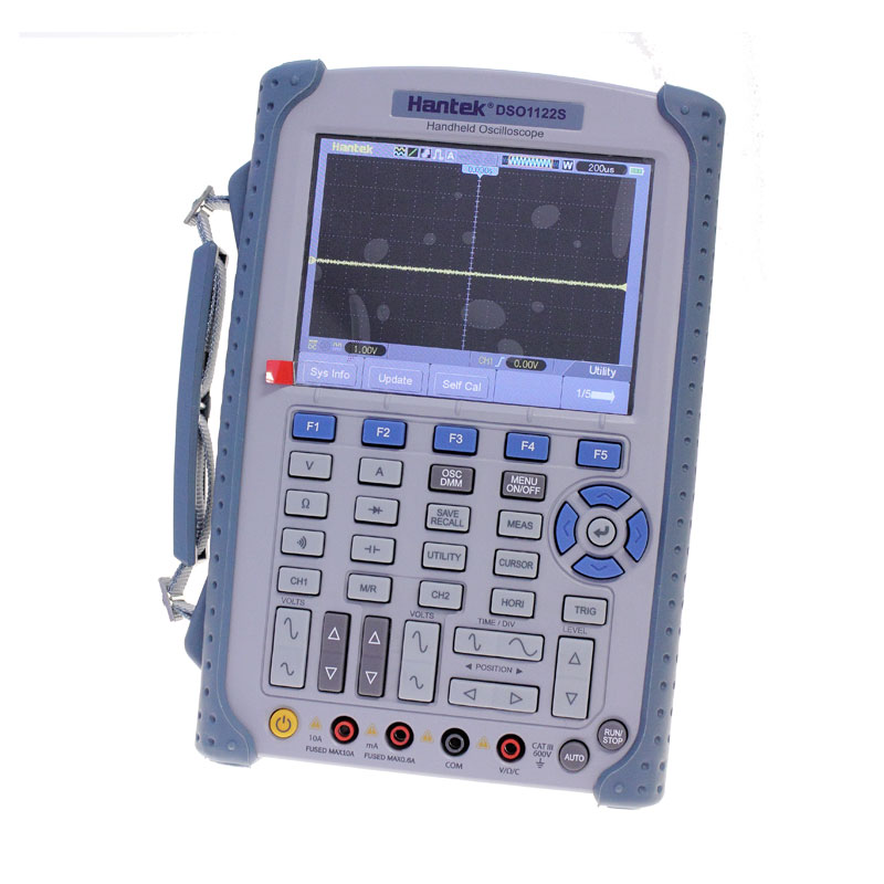
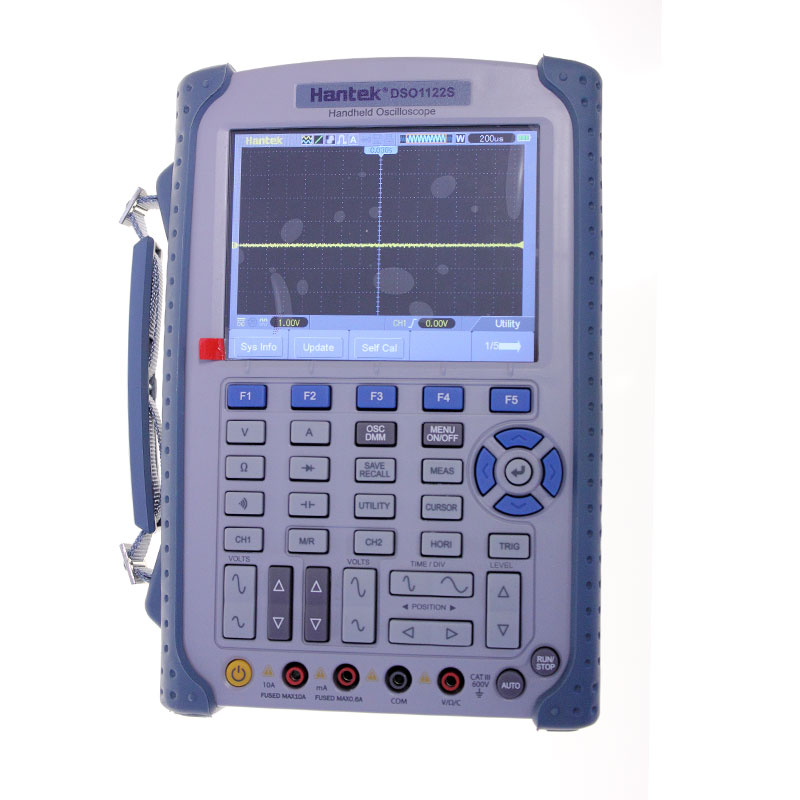
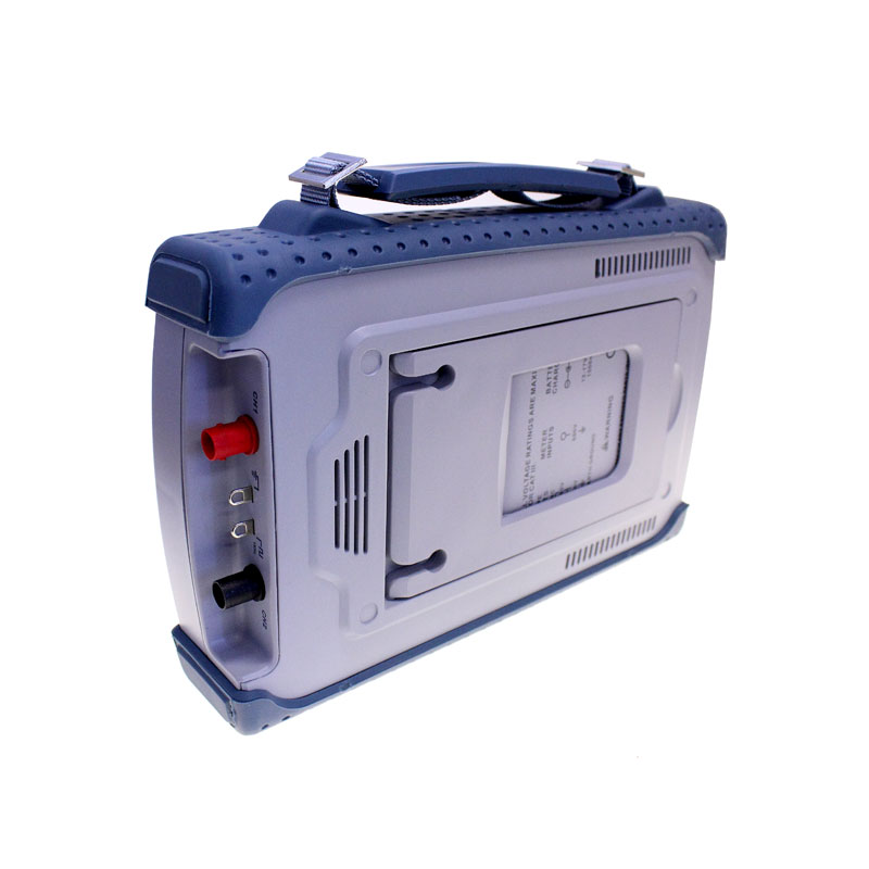
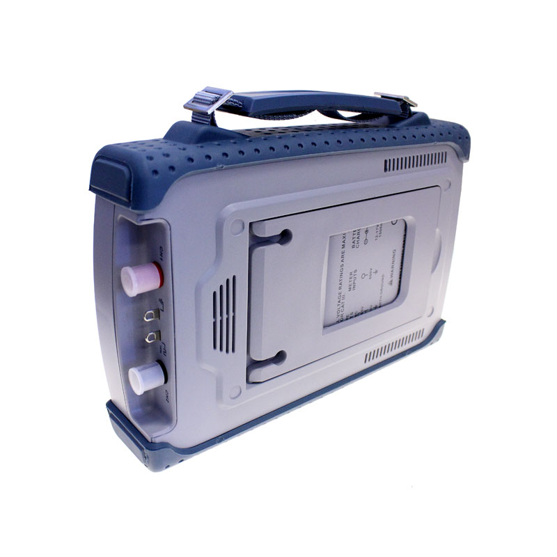
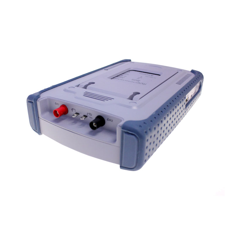
Hantek DSO 1122S (120 MHz) Digital Handheld Oscilloscope
Impressive design, intuitive control and high-resistance finish make oscilloscopes in the 1000S series useful aiders not only in field work, but also in hard industrial conditions. All Hantek oscilloscopes offer a great price/performance ratio at the low-end segment of measuring technology and the DSO 1022S is no exception. The advantages of Hantek Handheld over its rival products are the more than five times larger sampling memory, very good interference resistance, more accurate mulitmeter offering a larger number of ranges, a higher quality color display with a longer diagonal 5.6“ (14.5 cm), intuitive control and a long lasting battery (6 hours for a single recharge).
DSO 1122S – main features:
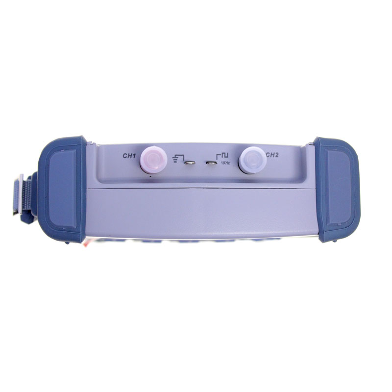
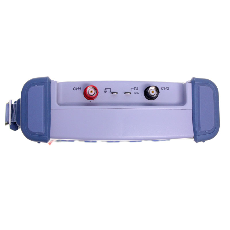
- Isolated Channels
- Bandwidth: 120 MHz
- Rise Time: 3.0ns
- Sampling rate: 1 GS/s
- Record Length: 1M
- Measurement record storage (supports bitmap and CSV format)
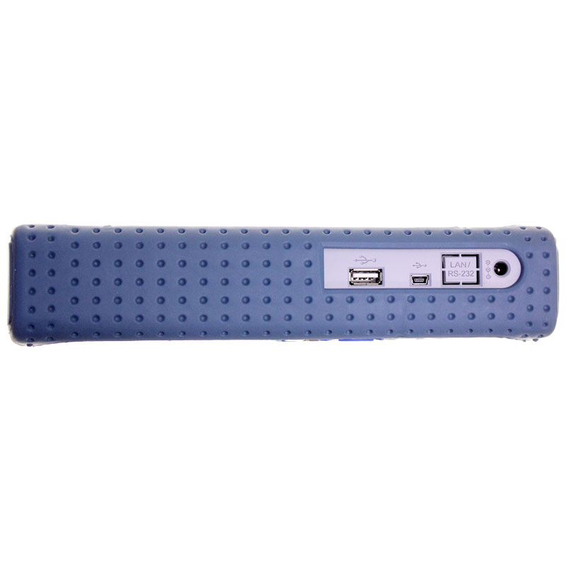
- USB Host: support removeable disk
- Zoom function
- Multimeter function
- 32 automatic measurements
- Measuring cursors
- Advanced trigger modes: Edge, Video, Pulse, Slope, Over time, Alternative
- Screen storage
- 5.6“ display with LED illumination; 640×480 point resolution
- Dual-Window Design
- LabVIEW support
- Applications development support – Visual C, Visual Basic
- Math functions including FFT
- Quick offset calibration
- LAN: Optional
- Dimensions (mm): 240(L) x 165(W) x 50(H)
Multimeter parameters:
- Number of digits: 6000
- Measurement modes: U, I, R, f, diod test, continutity test
- Max. input voltage – AC: 600 V DC: 800 V
- Max. input current – AC: 10A DC: 10A
- True-RMS multimeter
- Input impedance: 10 M
- Isolated input: up to 1000 V
- Safety class: 1000 V CAT II and 600 V CAT III
Control Programme
The programme, which uses a pop-up menu, is user-friendly and easy to control. It is localized in English and includes a built-in help system. It features a whole range of standard functions frequently met with.
Linux support
- Kernel version – Linux2.6.30.4
- File system – Yaffs, Fat32
- Drivers – Sound Driver, Buzzer Driver, FPGA Driver, SPI Driver, USB Host Driver, LCD Driver, USB Massstorage Gadget Driver
- Applications – Busy Box 1.18.4, Mplayer, Watchdog, Gnupg1.4.11
- U-boot – u-boot-1.1.6
The device will meet the needs of measuring technology professionals, but also those of technical secondary school and college students as a multifunction aid for study. Its low price and quality technical design offer a high use value.
Oscilloscope Specifications
Horizontal
|
Sample Rate Range </td style=”border: 1px solid;”> |
1GS/s </td style=”border: 1px solid;”> |
|
|
Waveform Interpolation </td style=”border: 1px solid;”> |
(sin x)/x </td style=”border: 1px solid;”> |
|
|
Record Length </td style=”border: 1px solid;”> |
Maximum 1M samples per single-channel; maximum 512K samples per dual-channel (4K,16K,40K optional) </td style=”border: 1px solid;”> |
|
|
TIME/DIV Range </td style=”border: 1px solid;”> |
DSO1062S DSO1122S </td style=”border: 1px solid;”> |
DSO1152S DSO1202S </td style=”border: 1px solid;”> |
|
4ns/div to 40s/div, in a 2, 4, 8 sequence </td style=”border: 1px solid;”> |
2ns/div to 40s/div, in a 2, 4, 8 sequence </td style=”border: 1px solid;”> |
|
|
Sample Rate and Delay Time Accuracy </td style=”border: 1px solid;”> |
±50ppm over any ≥1ms time interval </td style=”border: 1px solid;”> |
|
|
Delta Time Measurement Accuracy (Full Bandwidth) </td style=”border: 1px solid;”> |
Single-shot, Normal mode ± (1 sample interval +100ppm × reading + 0.6ns) </td style=”border: 1px solid;”> |
|
|
>16 averages ± (1 sample interval + 100ppm × reading + 0.4ns) </td style=”border: 1px solid;”> |
||
|
Sample interval = s/div ÷ 200 </td style=”border: 1px solid;”> |
||
|
Position Range </td style=”border: 1px solid;”> |
DSO1062S DSO1122S </td style=”border: 1px solid;”> |
|
|
4ns/div to 8ns/div </td style=”border: 1px solid;”> |
(-8div × s/div) to 20ms </td style=”border: 1px solid;”> |
|
|
20ns/div to 80μs/div </td style=”border: 1px solid;”> |
(-8div × s/div) to 40ms </td style=”border: 1px solid;”> |
|
|
200μs/div to 40s/div </td style=”border: 1px solid;”> |
(-8div × s/div) to 400s </td style=”border: 1px solid;”> |
|
|
DSO1152S DSO1202S </td style=”border: 1px solid;”> |
||
|
2ns/div to 10ns/div </td style=”border: 1px solid;”> |
(-4div × s/div) to 20ms </td style=”border: 1px solid;”> |
|
Vertical
|
A/D Converter </td style=”border: 1px solid;”> |
8-bit resolution, each channel sampled simultaneously </td style=”border: 1px solid;”> |
|||
|
VOLTS Range </td style=”border: 1px solid;”> |
2mV/div to 5V/div at input BNC </td style=”border: 1px solid;”> |
|||
|
Position Range </td style=”border: 1px solid;”> |
2mV/div to 200mV/div, ±2V >200mV/div to 5V/div, ±50V </td style=”border: 1px solid;”> |
|||
|
Analog Bandwidth in Normal and Average modes at BNC or with probe, DC Coupled </td style=”border: 1px solid;”> |
2mV/div to 20mV/div, ±400mV 50mV/div to 200mV/div, ±2V 500mV/div to 2V/div, ±40V 5V/div, ±50V </td style=”border: 1px solid;”> |
|||
|
Selectable Analog Bandwidth Limit, typical </td style=”border: 1px solid;”> |
20MHz </td style=”border: 1px solid;”> |
|||
|
Low Frequency Response (-3db) </td style=”border: 1px solid;”> |
≤10Hz at BNC </td style=”border: 1px solid;”> |
|||
|
Rise Time at BNC, typical </td style=”border: 1px solid;”> |
DSO1062S </td style=”border: 1px solid;”> |
DSO1122S </td style=”border: 1px solid;”> |
DSO1152S </td style=”border: 1px solid;”> |
DSO1202S </td style=”border: 1px solid;”> |
|
≤5.8ns </td style=”border: 1px solid;”> |
<3.0ns </td style=”border: 1px solid;”> |
≤2.3ns </td style=”border: 1px solid;”> |
<1.8ns </td style=”border: 1px solid;”> |
|
|
DC Gain Accuracy </td style=”border: 1px solid;”> |
±3% for Normal or Average acquisition mode, 5V/div to 10mV/div ±4% for Normal or Average acquisition mode, 5mV/div to 2mV/div </td style=”border: 1px solid;”> |
|||
|
DC Measurement Accuracy, Average Acquisition Mode </td style=”border: 1px solid;”> |
Measurement Type: Average of ≥16 waveforms with vertical position at zero Accuracy: ± (3% × reading + 0.1div + 1mV) when 10mV/div or greater is selected </td style=”border: 1px solid;”> |
|||
|
Measurement Type: Average of ≥16 waveforms with vertical position not at zero Accuracy: ± [3% × (reading + vertical position) + 1% of vertical position + 0.2div] Add 2mV for settings from 2mV/div to 200mV/div; add 50mV for settings from 200mV/div to 5V/div </td style=”border: 1px solid;”> |
||||
|
Volts Measurement Repeatability, Average Acquisition Mode </td style=”border: 1px solid;”> |
Delta volts between any two averages of ≥16 waveforms acquired under same setup and ambient conditions </td style=”border: 1px solid;”> |
Trigger
|
Trigger Sensitivity (Edge Trigger Type) </td style=”border: 1px solid;”> |
Coupling </td style=”border: 1px solid;”> |
Sensitivity </td style=”border: 1px solid;”> |
||||||
|
DC </td style=”border: 1px solid;”> |
Source </td style=”border: 1px solid;”> |
DSO1062S DSO1122S </td style=”border: 1px solid;”> |
DSO1152S DSO1202S </td style=”border: 1px solid;”> |
|||||
|
CH1 CH2 </td style=”border: 1px solid;”> |
1div from DC to 10MHz; </td style=”border: 1px solid;”> |
1.5div from 10MHz to 100MHz; </td style=”border: 1px solid;”> |
||||||
|
1.5div from 10MHz to Full </td style=”border: 1px solid;”> |
2div from 100MHz to Full </td style=”border: 1px solid;”> |
|||||||
|
AC </td style=”border: 1px solid;”> |
Attenuates signals below 10Hz </td style=”border: 1px solid;”> |
|||||||
|
HF Reject </td style=”border: 1px solid;”> |
Attenuates signals above 80kHz </td style=”border: 1px solid;”> |
|||||||
|
LF Reject </td style=”border: 1px solid;”> |
Same as the DC-coupled limits for frequencies above 150kHz; attenuates signals below 150kHz </td style=”border: 1px solid;”> |
|||||||
|
Trigger Level Range </td style=”border: 1px solid;”> |
Source </td style=”border: 1px solid;”> |
Range </td style=”border: 1px solid;”> |
||||||
|
CH1, CH2 </td style=”border: 1px solid;”> |
±8 divisions from center of screen </td style=”border: 1px solid;”> |
|||||||
|
Trigger Level Accuracy, typical (Accuracy is for signals having rise and fall times ≥20ns) </td style=”border: 1px solid;”> |
Source </td style=”border: 1px solid;”> |
Accuracy </td style=”border: 1px solid;”> |
||||||
|
CH1、CH2 </td style=”border: 1px solid;”> |
0.2div × volts/div within ±4 divisions from center of screen </td style=”border: 1px solid;”> |
|||||||
|
Set Level to 50%, typical </td style=”border: 1px solid;”> |
Operates with input signals ≥50Hz </td style=”border: 1px solid;”> |
|||||||
|
Slope Trigger </td style=”border: 1px solid;”> |
||||||||
|
Slope Trigger Mode </td style=”border: 1px solid;”> |
Trigger when < (Less than), > (Greater than), = (Equal), or ≠ (Not Equal); Positive slope or Negative slope </td style=”border: 1px solid;”> |
|||||||
|
Slope Trigger Point </td style=”border: 1px solid;”> |
Equal: The oscilloscope triggers when the waveform slope is equal to the set slope. Not Equal: The oscilloscope triggers when the waveform slope is not equal to the set slope. Less than: The oscilloscope triggers when the waveform slope is less than the set slope. Greater than: The oscilloscope triggers when the waveform slope is greater than the set slope. </td style=”border: 1px solid;”> |
|||||||
|
Time Range </td style=”border: 1px solid;”> |
Selectable from 20ns to 10s </td style=”border: 1px solid;”> |
|||||||
|
Overtime Trigger </td style=”border: 1px solid;”> |
The leading edge: Rising edge or Falling edge; Time Setting: 20-10s </td style=”border: 1px solid;”> |
|||||||
|
Alter Trigger </td style=”border: 1px solid;”> |
||||||||
|
CH1 </td style=”border: 1px solid;”> |
Internal Trigger: Edge, Pulse Width, Video, Slope </td style=”border: 1px solid;”> |
|||||||
|
CH2 </td style=”border: 1px solid;”> |
Internal Trigger: Edge, Pulse Width, Video, Slope </td style=”border: 1px solid;”> |
|||||||
|
Trigger Frequency Counter </td style=”border: 1px solid;”> |
||||||||
|
Readout Resolution </td style=”border: 1px solid;”> |
6 digits </td style=”border: 1px solid;”> |
|||||||
|
Accuracy (typical) </td style=”border: 1px solid;”> |
±30ppm (including all frequency reference errors and ±1 count errors) </td style=”border: 1px solid;”> |
|||||||
|
Frequency Range </td style=”border: 1px solid;”> |
AC coupled, from 4Hz minimum to rated bandwidth </td style=”border: 1px solid;”> |
|||||||
|
Signal Source </td style=”border: 1px solid;”> |
Pulse Width or Edge Trigger modes: all available trigger sources The Frequency Counter measures trigger source at all times, including when the oscilloscope acquisition pauses due to changes in the run status, or acquisition of a single shot event has completed. Pulse Width Trigger mode: The oscilloscope counts pulses of significant magnitude inside the 1s measurement window that qualify as triggerable events, such as narrow pulses in a PWM pulse train if set to < mode and the width is set to a relatively small time. Edge Trigger mode: The oscilloscope counts all edges of sufficient magnitude and correct polarity. Video Trigger mode: The Frequency Counter does not work. </td style=”border: 1px solid;”> |
|||||||
Acquisition
|
Acquisition Modes </td style=”border: 1px solid;”> |
Normal, Peak Detect, and Average </td style=”border: 1px solid;”> |
|
|
Acquisition Rate, typical </td style=”border: 1px solid;”> |
Up to 2000 waveforms per second per channel (Normal acquisition mode, no measurement) </td style=”border: 1px solid;”> |
|
|
Single Sequence </td style=”border: 1px solid;”> |
Acquisition Mode </td style=”border: 1px solid;”> |
Acquisition Stop Time </td style=”border: 1px solid;”> |
|
Normal, Peak Detect </td style=”border: 1px solid;”> |
Upon single acquisition on all channels simultaneously </td style=”border: 1px solid;”> |
|
|
Average </td style=”border: 1px solid;”> |
After N acquisitions on all channels simultaneously, N can be set to 4, 8, 16, 32, 64 or 128 </td style=”border: 1px solid;”> |
|
Inputs
|
Input Coupling </td style=”border: 1px solid;”> |
DC, AC or GND </td style=”border: 1px solid;”> |
|
|
Input Impedance, DC coupled </td style=”border: 1px solid;”> |
1MΩ±2% in parallel with 20pF±3pF </td style=”border: 1px solid;”> |
|
|
Probe Attenuation </td style=”border: 1px solid;”> |
1X, 10X </td style=”border: 1px solid;”> |
|
|
Supported Probe Attenuation Factors </td style=”border: 1px solid;”> |
1X, 10X, 100X, 1000X </td style=”border: 1px solid;”> |
|
|
Maximum Input Voltage </td style=”border: 1px solid;”> |
Overvoltage Category </td style=”border: 1px solid;”> |
Maximum Voltage </td style=”border: 1px solid;”> |
|
CAT I and CAT II </td style=”border: 1px solid;”> |
300VRMS (10×), Installation Category </td style=”border: 1px solid;”> |
|
|
CAT III </td style=”border: 1px solid;”> |
150VRMS (1×) </td style=”border: 1px solid;”> |
|
|
Installation Category II: derate at 20dB/decade above 100kHz to 13V peak AC at 3MHz* and above. For non-sinusoidal waveforms, peak value must be less than 450V. Excursion above 300V should be of less than 100ms duration. RMS signal level including all DC components removed through AC coupling must be limited to 300V. If these values are exceeded, damage to the oscilloscope may occur. </td style=”border: 1px solid;”> |
||
Measurements
|
Cursors </td style=”border: 1px solid;”> |
Voltage difference between cursors: △V Time difference between cursors: △T Reciprocal of △T in Hertz (1/ΔT) </td style=”border: 1px solid;”> |
|
Automatic Measurements </td style=”border: 1px solid;”> |
Frequency, Period, Mean, Peak-to-peak, Cycle RMS, PRMS, Minimum, Maximum, Rise Time, Fall Time, + Width, – Width, + Duty, – Duty, Base, Top, Middle, Amplitude, Overshoot, Preshoot, Pmean, FOVShoot, RPREShoot, BWidth, Delay 1-2 ↑, Delay 1-2 ↓, LFF, LFR, LRF, LRR, FFR, EFRF </td style=”border: 1px solid;”> |
General Specifications
|
Display </td style=”border: 1px solid;”> |
|
|
Display Type </td style=”border: 1px solid;”> |
5.6 Inch width TFT Display </td style=”border: 1px solid;”> |
|
Display Resolution </td style=”border: 1px solid;”> |
480 (Vertical) X 640 (Horizontal) pixels </td style=”border: 1px solid;”> |
|
Display Contrast </td style=”border: 1px solid;”> |
Adjustable (16 gears) with the progress bar </td style=”border: 1px solid;”> |
|
Probe Compensator Output </td style=”border: 1px solid;”> |
|
|
Output Voltage, typical </td style=”border: 1px solid;”> |
About 5Vpp into ≥1MΩ load </td style=”border: 1px solid;”> |
|
Frequency, typical </td style=”border: 1px solid;”> |
1kHz </td style=”border: 1px solid;”> |
|
Power Supply </td style=”border: 1px solid;”> |
|
|
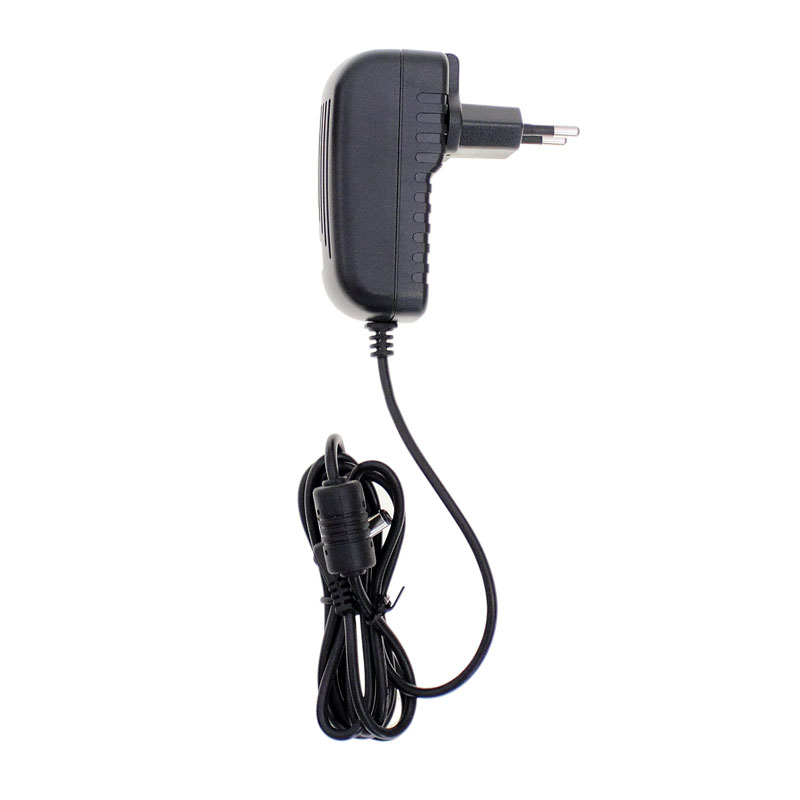
Switching Adatper </td style=”border: 1px solid;”> |
AC Input:100-240VACRMS,0.6A MAX,50Hz/60Hz; DC Output:12V,2A </td style=”border: 1px solid;”> |
|
DC Input </td style=”border: 1px solid;”> |
DC8.5-15V,2A </td style=”border: 1px solid;”> |
|
Power Consumption </td style=”border: 1px solid;”> |
<30W </td style=”border: 1px solid;”> |
Meter Mode
|
Maximum Resolution </td style=”border: 1px solid;”> |
6000 Counts </td style=”border: 1px solid;”> |
||
|
DMM Testing Modes </td style=”border: 1px solid;”> |
Voltage, Current, Resistance, Capacitance, Diode & Continuity </td style=”border: 1px solid;”> |
||
|
Maximum Input Voltage </td style=”border: 1px solid;”> |
AC : 600V DC : 800V </td style=”border: 1px solid;”> |
||
|
Maximum Input Current </td style=”border: 1px solid;”> |
AC : 10A DC : 10A </td style=”border: 1px solid;”> |
||
|
Input Impedance </td style=”border: 1px solid;”> |
10MΩ </td style=”border: 1px solid;”> |
||
|
Meter Specification Range </td style=”border: 1px solid;”> |
Accuracy </td style=”border: 1px solid;”> |
Resolution </td style=”border: 1px solid;”> |
|
|
DC Voltage </td style=”border: 1px solid;”> |
60.00mV(manual) </td style=”border: 1px solid;”> |
±1%±1digit </td style=”border: 1px solid;”> |
10uV </td style=”border: 1px solid;”> |
|
600.0mV </td style=”border: 1px solid;”> |
100uV </td style=”border: 1px solid;”> |
||
|
6.000V </td style=”border: 1px solid;”> |
1mV </td style=”border: 1px solid;”> |
||
|
60.00V </td style=”border: 1px solid;”> |
10mV </td style=”border: 1px solid;”> |
||
|
600.0V </td style=”border: 1px solid;”> |
100mV </td style=”border: 1px solid;”> |
||
|
800V </td style=”border: 1px solid;”> |
1V </td style=”border: 1px solid;”> |
||
|
AC Voltage </td style=”border: 1px solid;”> |
60.00mV(manual) </td style=”border: 1px solid;”> |
±1%±3digit </td style=”border: 1px solid;”> |
10uV </td style=”border: 1px solid;”> |
|
600.0mV(manual) </td style=”border: 1px solid;”> |
100uV </td style=”border: 1px solid;”> |
||
|
6.000V </td style=”border: 1px solid;”> |
1mV </td style=”border: 1px solid;”> |
||
|
60.00V </td style=”border: 1px solid;”> |
10mV </td style=”border: 1px solid;”> |
||
|
600.0V </td style=”border: 1px solid;”> |
100mV </td style=”border: 1px solid;”> |
||
|
DC Current </td style=”border: 1px solid;”> |
60.00mA </td style=”border: 1px solid;”> |
±1.5%±1digit </td style=”border: 1px solid;”> |
10uA </td style=”border: 1px solid;”> |
|
600.0mA </td style=”border: 1px solid;”> |
±1%±1digit </td style=”border: 1px solid;”> |
100uA </td style=”border: 1px solid;”> |
|
|
6.000A </td style=”border: 1px solid;”> |
±1.5%±3digit </td style=”border: 1px solid;”> |
1mA </td style=”border: 1px solid;”> |
|
|
10.00A </td style=”border: 1px solid;”> |
10mA </td style=”border: 1px solid;”> |
||
|
AC Current </td style=”border: 1px solid;”> |
60.00mA </td style=”border: 1px solid;”> |
±1.5%±3digit </td style=”border: 1px solid;”> |
10uA </td style=”border: 1px solid;”> |
|
600.0mA </td style=”border: 1px solid;”> |
±1%±1digit </td style=”border: 1px solid;”> |
100uA </td style=”border: 1px solid;”> |
|
|
6.000A </td style=”border: 1px solid;”> |
±1.5%±3digit </td style=”border: 1px solid;”> |
1mA </td style=”border: 1px solid;”> |
|
|
10.00A </td style=”border: 1px solid;”> |
10mA </td style=”border: 1px solid;”> |
||
|
Resistance </td style=”border: 1px solid;”> |
600.0 </td style=”border: 1px solid;”> |
±1%±1digit </td style=”border: 1px solid;”> |
0.1Ω </td style=”border: 1px solid;”> |
|
6.000K </td style=”border: 1px solid;”> |
1Ω </td style=”border: 1px solid;”> |
||
|
60.00K </td style=”border: 1px solid;”> |
10Ω </td style=”border: 1px solid;”> |
||
|
600.0K </td style=”border: 1px solid;”> |
100Ω </td style=”border: 1px solid;”> |
||
|
6.000M </td style=”border: 1px solid;”> |
1KΩ </td style=”border: 1px solid;”> |
||
|
60.00M </td style=”border: 1px solid;”> |
±1.5%±3digit </td style=”border: 1px solid;”> |
10KΩ </td style=”border: 1px solid;”> |
|
|
Capacitance </td style=”border: 1px solid;”> |
40.00nF </td style=”border: 1px solid;”> |
±1%±1digit </td style=”border: 1px solid;”> |
10pF </td style=”border: 1px solid;”> |
|
400.0nF </td style=”border: 1px solid;”> |
100pF </td style=”border: 1px solid;”> |
||
|
4.000uF </td style=”border: 1px solid;”> |
1nF </td style=”border: 1px solid;”> |
||
|
40.00uF </td style=”border: 1px solid;”> |
10nF </td style=”border: 1px solid;”> |
||
|
400.0uF </td style=”border: 1px solid;”> |
100nF </td style=”border: 1px solid;”> |
||
|
</td style=”border: 1px solid;”> |
Attention:The smallest capacitance value that can be measured is 5nF. </td style=”border: 1px solid;”> |
||
|
Diode </td style=”border: 1px solid;”> |
0V~2.0V </td style=”border: 1px solid;”> |
||
|
On-off Test </td style=”border: 1px solid;”> |
< 30Ω </td style=”border: 1px solid;”> |
||
Linux Feature
|
Kernel Version </td style=”border: 1px solid;”> |
Linux2.6.30.4 </td style=”border: 1px solid;”> |
|
Supported File system </td style=”border: 1px solid;”> |
Yaffs, Fat32 </td style=”border: 1px solid;”> |
|
Drivers </td style=”border: 1px solid;”> |
Sound Driver, Buzzer Driver, FPGA Driver, SPI Driver, USB Host Driver, LCD Driver, USB massstorage、gadget Driver </td style=”border: 1px solid;”> |
|
Linux Applications </td style=”border: 1px solid;”> |
busybox1.18.4, mplayer, watchdog, gnupg1.4.11 </td style=”border: 1px solid;”> |
|
U_boot Version </td style=”border: 1px solid;”> |
u-boot-1.1.6 </td style=”border: 1px solid;”> |
|
Sourcecode download website </td style=”border: 1px solid;”> |
www.hantek.com/download/handscope.zip </td style=”border: 1px solid;”> |
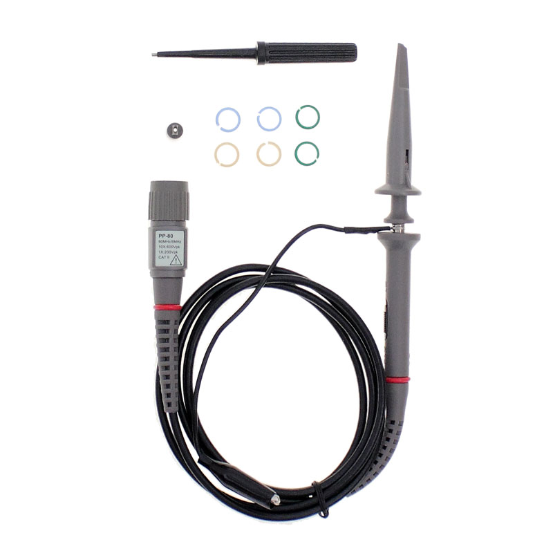
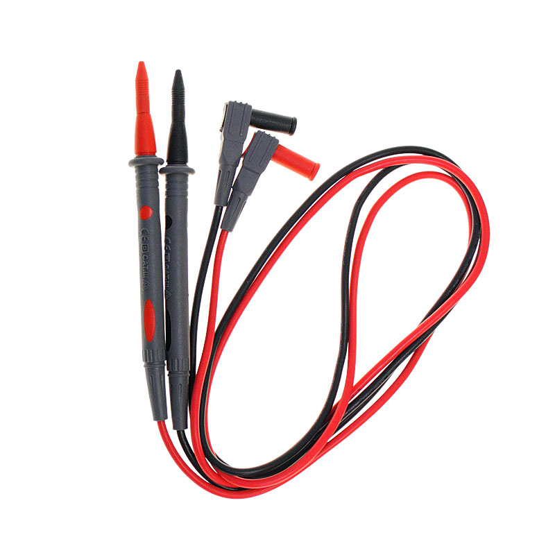
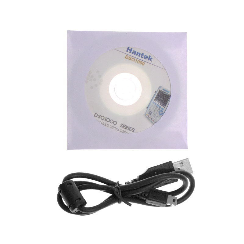
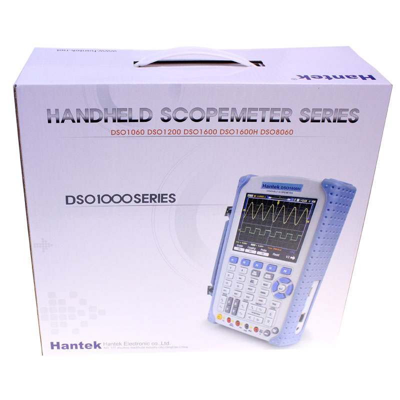
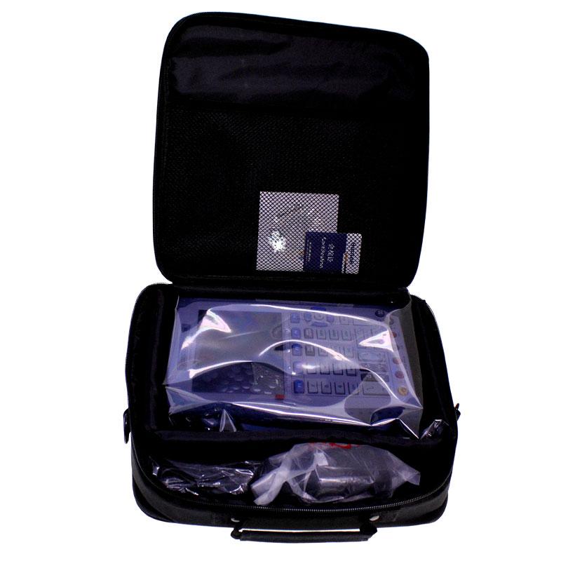
| Package contents |
Package includes:
</td style=”border: 1px solid;”> |
|---|
Additional information
| Weight | 1 kg |
|---|---|
| Warranty | |
| Model | |
| Parameters | <p class="Default"><strong>Oscilloscope Specifications</strong></p> |

Reviews
There are no reviews yet.